Introduction
In order to solve the problem of electricity consumption in weak electricity areas, and at the same time increase new energy energy conservation and emission reduction, it will bring very considerable benefits to users.
This document is written based on the relevant technical standards for energy storage power stations. Including a general description of the product, hardware environment, specific functional requirements and other relevant support information, relevant development tasks and relevant developers to carry out specific work based on this.
1.1 Project background
The project aims to build a 2016kWh microgrid energy storage system, 500kW energy storage converter and EMS. The energy storage converter, EMS and battery are placed in the container. The system design can take into account the charging and discharging characteristics of the lithium battery. The entire system needs to realize functions such as peak shaving and valley filling and load following.
1.2 Terminology
1> PCS (Power Covert System): Energy storage converter is a bidirectional converter device that performs inversion and rectification.
2> SOC (State Of Capacity): The remaining capacity of the battery, expressed as a percentage.
3>SOH (State Of Health): Battery pack health status, expressed as a percentage.
4>DOD (Depth Of Discharge): The depth of discharge of the battery, expressed as a percentage.
5>BMS (Battery Management System): Battery management system, responsible for the management and control of the battery part of the energy storage system.
6> EMS (Energy Management System): Energy management system, responsible for the management and control of energy storage converters, battery systems, air conditioning systems, fire protection systems, etc.
1.3 Reference standards
1> GB/T 3859.1-1993 Basic requirements for semiconductor converters
2> GB/T 3859.2- 2013 Semiconductor converters General requirements and grid commutated converters Part 1-2: Application guidelines
3> GB/T 13422-2013 Semiconductor power converters Electrical test methods
4> GB/T 2423.1-2001 Electrical and electronic products Environmental testing Part 2: Test methods Test A: Low temperature
5> GB/T 2423.2-2001 Electrical and electronic products Environmental testing Part 2: Test methods Test B: High temperature
6> GB/T 2423.3-2006 Electrical and electronic products Environmental testing Part 2: Test method Test Cab: Constant humidity and heat test
7> GB/T 2423.4-2008 Electrical and electronic products Environmental testing Part 2: Test method test Db alternating damp heat (12h+12h cycle)
8> GB/T 12325-2008 Power quality supply voltage deviation
9> GB/T 12326-2008 Power quality Voltage fluctuation and flicker
10> GB/T 14549-1993 Power Quality Public Grid Harmonics
11> GB/T 15543-2008 Power quality three-phase voltage unbalance
12> GB/T 15945-2008 Power quality Power system frequency deviation
13> GB/Z 17625.3-2000 Electromagnetic compatibility limits Limits on voltage fluctuations and flickers produced by equipment with a rated current greater than 16A in low-voltage power supply systems
14> DL/ T860 (all) remote control equipment and systems (series standards)
15> DL/T634 (all) Telecontrol equipment and systems (series standards)
16> DL/T645-1997 Multifunctional electric energy meter communication protocol
17> DL5002-2005 Technical regulations for regional power grid dispatching automation design
18> DL548-1994 Lightning Protection Operation and Management Regulations for Power System Communication Stations
19> GB/T13729-2002 General technical conditions for remote control terminals
2.1.2 Battery Management System (BMS) Design
Taking into account communication capabilities and system security, the battery management system adopts a three-layer architecture. The basic system architecture is as follows:
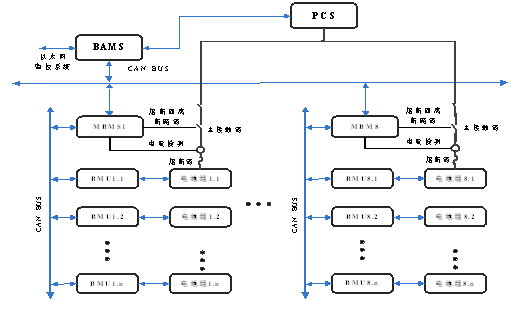
Illustrate:
The slave controller collects the voltage and temperature of each group of cells.
The master control obtains slave control data through communication, and collects voltage, current, etc.
2.1.3 Battery management system functions
BMS has the following functions:
(1) High-precision monitoring function of battery analog quantity
At the BMU level, single module voltage is detected in real time. MBMS detects battery cluster charge and discharge current, system total voltage, system insulation, etc.
(2) SOC estimation
Through current integration, basic SOC estimation is achieved. Combined with the filling and emptying correction functions, the SOC accuracy can be effectively improved. In addition, capacity calibration and SOC calibration are completed independently under the management of BAMS. Through its own algorithm, the latest corrected battery system capacity and SOC calibration value are obtained, and this is used as the basis for subsequent battery charge and discharge management. The error of the SOC value obtained by this is small, and at the same time, it will increase during the long-term accumulation process. Avoid SOC error amplification.
(3) Battery system alarm and protection functions
When the voltage, current, temperature and other analog quantities of the battery system exceed the safety protection threshold, the battery management system will isolate the fault, remove the problematic battery cluster from operation, and report the protection information and display it locally.
2.2 Energy storage converter (PCS) selection and design
2.2.1 Introduction to energy storage converter functions
In the energy storage system constructed in this plan, in addition to the bidirectional inverter function, the energy storage converter can also support the power grid, ensure the stable operation of the power grid system, provide resistance to short-term impact, smooth power supply, energy storage, and reduce power consumption. Peaks fill valleys.
Energy storage devices have the following functions:
(1) Active power control function, the PCS energy storage device can control its active power output according to the instructions of the microgrid operation control system. In order to realize the active power adjustment function, the battery energy storage system can receive and real-time track and execute the active power control signal sent by the microgrid operation control system, automatically adjust the active output according to the microgrid operation control system control instructions and other signals, and output the active power and the set value. The deviation does not exceed 3%.
(2) Voltage/reactive power adjustment function, the PCS energy storage device can track and adjust the reactive power output in real time according to signals such as microgrid operation control system control instructions. Its parameters such as reactive power and power factor can be controlled by the microgrid operation control system. Remote settings.
(3) Off-grid V/F control function. The PCS energy storage device has voltage and frequency adjustment functions in off-grid mode. It can automatically set the rated voltage and rated frequency to start and run, and can also receive external voltage given instructions. and frequency given instructions to adjust voltage and frequency.
(4) Off-grid soft start function. The PCS energy storage device can start smoothly in off-grid mode, reducing the impact current and the impact on the microgrid. The system operates stably from standby to rated voltage in less than 2 seconds.
(5) The PCS energy storage device has an active islanding detection function. In the islanding state, it can detect the islanding state within 500ms and report fault information through the monitoring system.
(6) The PCS energy storage device has a certain ability to withstand abnormal voltage. The allowable deviation of the three-phase voltage at the AC output terminal is +15% and -15% of the rated voltage (can be set).
(7) The PCS energy storage device has a certain ability to withstand system frequency abnormalities in grid-connected mode and can operate under the grid frequency deviation shown in Table 6-2 (can be set).
(8) The cooling method of PCS energy storage device is air cooling.
(9) The PCS energy storage device has two operating modes: grid-connected and off-grid, and can realize the on-grid and off-grid switching function according to conditions (it needs to cooperate with STS to realize the automatic switching on and off the grid (power-off time <15ms)). In the network operation mode, it meets the relevant requirements of power quality. Note: Off-grid load capacity is determined based on load characteristics.
(10) The PCS energy storage device meets the battery’s power quality requirements when charging the battery. During constant current charging, the steady current accuracy is ≤1% and the current ripple is ≤5%. During constant voltage charging, the voltage stabilization accuracy is ≤1% and the voltage ripple is ≤2.5%.
(11) After the PCS energy storage device is connected to the power grid, the three-phase voltage imbalance at the public connection point does not exceed the limit specified in GB/T 15543-2008 "Power Quality Three-phase Voltage Imbalance", and the negative sequence at the public connection point The voltage imbalance should not exceed 2%, and it should not exceed 4% in the short term; the negative sequence voltage imbalance caused by the PCS energy storage device should not exceed 1.3%, and it should not exceed 2.6% in the short term.
(12) The PCS energy storage device has human-machine interface and communication functions, and staff can operate it locally and remotely.
(13) The PCS energy storage device has a certain ability to withstand overcurrent. 105%~115% 10min, 115%~125% 1min, 125%~150% 200ms, when the output current of the PCS energy storage device is 105%~115% of the rated current, run continuously for 10min; when the output current of the PCS energy storage device When the output current of the PCS energy storage device is 115%~125% of the rated current, it will run continuously for 1 minute. When the output current of the PCS energy storage device is 125%~150% of the rated current, it will run continuously for 200ms.
(14) PCS energy storage device has overheating protection function. In any case where the main heating components inside the PCS energy storage device: such as IGBT temperature, transformer temperature, and reactor temperature exceed the allowable value, the PCS energy storage device stops supplying power to the grid. After returning to normal, the PCS energy storage device can work normally.
(15) The PCS energy storage device has three-phase unbalance and phase protection functions. When the three-phase AC output side of the PCS energy storage device is unbalanced or the phase detected after being connected to the power grid is wrong, the PCS energy storage device stops working.
(16) PCS energy storage device can form a microgrid system. The PCS energy storage device works off-grid and can operate in conjunction with photovoltaic inverters, wind power generation equipment, loads, etc. to form a microgrid. The PCS energy storage device can output stable voltage values and frequencies. When the three-phase load imbalance of the PCS is less than 15%, the output voltage value and frequency can remain stable. When the photovoltaic inverter, wind power generation equipment, other power sources and loads are put in (cut off) at will, the output voltage value and The frequency change and recovery meet relevant power quality requirements.
(17) The PCS has two power sources, the DC side and the AC side. When not in use for a long time, the DC side and AC side switches need to be disconnected to avoid battery loss.
(18) The standard machine does not have the insulation detection function. You need to select an insulation detector before placing an order to have the DC insulation detection function.
(19) PCS has a DC source working mode (this working mode needs to be confirmed before placing an order). It can establish a stable DC bus by connecting to AC power. However, PCS cannot establish a DC bus with load. The PCS needs to establish a stable DC bus first. Then put the load on the DC bus.
2.3 Energy Management System (EMS) Design
2.3.1 Introduction to EMS system functions
The energy management system is an important part of the energy storage system. It provides data management, monitoring, control and optimization for the microgrid dispatch control center to ensure the stable and efficient operation of the energy storage system. The energy management system provides power and voltage set points for each energy controller within the energy storage system; ensures that the heat load and electrical load requirements in the system are met; ensures that the system meets the operating agreement with the main network system; and that energy consumption is consistent with that of the main network system as much as possible. Minimize system loss; provide logic and control methods for islanding operation and reclosing in case of system failure (adding parallel grid switching unit), etc.
EMS has 4 485 communication ports, 2 CAN communication ports, and 4 Ethernet interfaces. Electric meters, diesel engines, and air conditioners are connected using 485 communication methods. PCS, photovoltaic inverter, BMS, IO port expansion box, are connected through Ethernet communication. Fire controllers and contactors feedback information and control through IO port node signals.
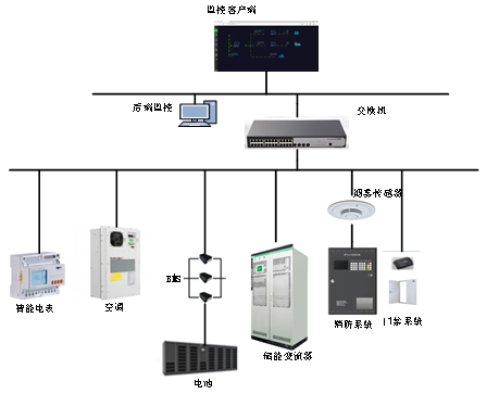
2.3.2 EMS networking architecture
In the energy storage system, the EMS communication topology is divided into two layers. The top layer is the centralized monitoring system. The bottom layer equipment: a 50kW energy storage converter, load meter, battery management system (BMS), environmental monitoring equipment, and fire protection system. , air conditioning or access control systems are all connected to the monitoring system.
2.3.3 EMS function design
(1) Operation logic
1) Photovoltaic power generation gives priority to powering building loads. If there is sufficient electric energy to charge the energy storage, there will be surplus electric energy after the energy storage is full, and then the electricity will be sent to the grid;
2) When there is no power in the photovoltaic system at night, the stored electricity is released for the load (it cannot be released to the grid)
3) Cycle in sequence;
4) In the event of a mains power outage, the stored energy is released for use by the load, and Huawei's grid-connected inverter is started to supply power to the load and energy storage. (When the mains power is outage, photovoltaic and energy storage cannot be used outside the mains power supply. Power transmission, circuit breaker with remote operation).
(2) Control strategy
The energy storage energy management system should realize functions such as peak shaving and valley filling, reverse power protection, etc.
1) Peak shaving and valley filling: Automatically control the energy storage system to charge during periods of low electricity prices and discharge during periods of peak electricity prices to perform peak and valley arbitrage.
2) Reverse power protection: During the discharge period of the energy storage system, the real-time discharge power of the energy storage system is controlled according to the reverse power protection threshold (the parameter value is open to users). When the transformer load power is lower than the reverse power protection setting threshold, the energy storage system power is reduced in steps of 5kW of the energy storage converter power until the transformer load power is higher than the reverse power protection setting threshold.
(3) Basic functions
1) It can display the current dischargeable amount, rechargeable amount, maximum discharge power, current discharge power, dischargeable time, today's total charge amount, and today's total discharge amount of energy storage in real time.
2) Remote signaling: It can remotely communicate the operating status and alarm information of the AC and DC bidirectional converter. The protection signals include: low voltage protection, overvoltage protection, phase loss protection, low frequency protection, overfrequency protection, overcurrent protection, Device abnormality protection, battery pack abnormal working condition protection, and over-temperature protection.
3) Telemetry: It can remotely measure the battery voltage, battery charge and discharge current, AC voltage, input and output power of the AC and DC bidirectional converter;
4) Remote adjustment: It can remotely adjust the battery charge and discharge time, charge and discharge current, and battery protection voltage to realize remote adjustment of relevant parameters of the AC and DC bidirectional converter;
Remote control: It can remotely control the battery charging and remote battery discharging functions of the bidirectional converter. (Cloud control is temporarily not available due to security reasons)
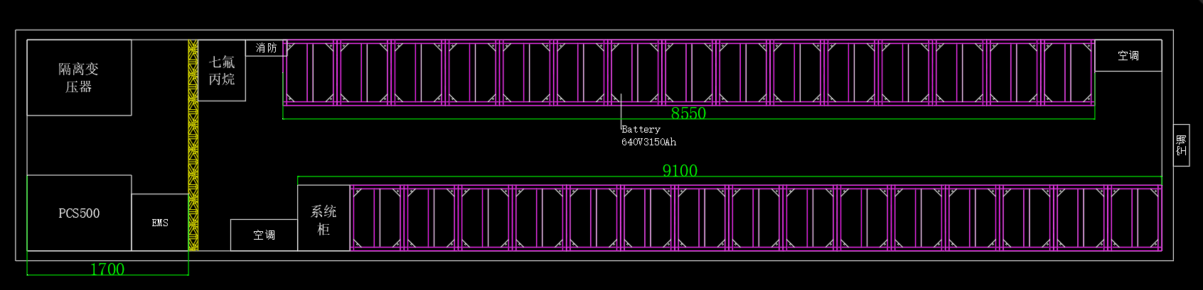
2.4 Container design
2.4.1 Container layout design
The plan uses a 40-foot standard container as the carrier. The actual design shall prevail. The following is the layout of the 40-foot container. The dimensions inside the container are the recommended specifications: 11980mm (W) * 2230mm (D) * 2320mm (H), including battery rack, Fire cabinet, BMS control cabinet, air conditioner, lighting, smoke detector, etc. The power distribution room contains a set of 630kW PCS, EMS cabinet (including power distribution part), fire control box, lighting and smoke detector, etc.
2.4.2 System cooling solution
2.4.2.1 Battery room cooling solution
Air conditioners are used for heat dissipation. The selection of air conditioners needs to consider the heat generated by the battery during charging and discharging, the heat transfer of the container box, etc. Based on the above, two air conditioners with a cooling capacity of 5kW can be used.
2.4.2.2 Heat dissipation solution for power distribution room
The main equipment is the PCS and EMS system, which can be air-cooled for heat dissipation.
2.4.3 Fire protection plan
The battery room uses a cabinet-type heptafluoropropane fire extinguisher to ensure that the gas fills the entire battery room within 8 seconds to effectively extinguish the fire. It is also equipped with an audible and visual alarm system and a gas discharge indicator light.
Considering that the protection of the cabinet is relatively complete, the power distribution room has complete overheating protection, short-circuit protection, etc. Fire is a very extreme working condition, and there is a smoke sensor. Once an alarm signal is detected, the system will shut down. Dry powder fire extinguishers can be used here. Standby fire extinguishing.
2.4.4 Lighting scheme
Configure conventional lighting and emergency lighting. When the door is opened, the conventional lighting is turned on. After the door is closed, the conventional lighting is turned off. When the door is opened and the conventional lighting is powered off, the emergency lighting is turned on. The emergency lighting time is guaranteed to be no less than 30 minutes.
3Equipment List
| Serial number | Device name | Brand | Model | Unit | Quantity |
| 1 | Container | 40 feet (fire protection, air conditioning, smoke detectors, integrated wiring, etc.) | Set | 1 | |
| 2 | Industrial air conditioner | 5kw | Tower | 2 | |
| 3 | Interior decoration | Insulation rock wool + lighting weak current | Set | 1 | |
| 4 | Energy storage converter | PCS-500k | Tower | 1 | |
| 5 | 2016kWh lithium battery system | Luyang | For GBP640V3150Ah batteries, the battery pack uses 10 series and 3 parallel, 32v315Ah, a single cluster has 20 battery packs per high voltage pack, a total of 10 clusters, and uses 3 7-layer battery racks. The system has a total of 30 7-layer battery racks, 640v3150ah, 2016kwh , SOC 90%, warranty 8 years/4000 cycles | Set | 1 |
| 6 | Freight | Set | 1 |
Illustrate:
a. The project implementation location, construction, installation issues and related accessories involved in this project have not been considered;
b. Use outdoor container-type installation, and the container specifications need to be determined according to the specific implementation conditions;
c. The capacity of each component must be based on the final contract quantity;